EQUIPMENT FOR RADIO RELAY LINE OF DATA TRANSMISSION «MARK-RRL»

It is intended for organization of few and multi channels transmission radio lines of; telephone, computer, video and audio information.

Features of the given equipment are:

  • small dimensions and weight;
  • low power consumption;
  • sweeping time(15 min);
  • mobility.


SPECIFICATIONS


Parameter  VHF   UHF   SHF   EHF  
Max. power consumption 40 W 40 W 40 W 20 W
Output power of transmitter 5 W 5 W  200 mW  20 mW
Signal/noise ratio at input of receiver  minus 3 dB  minus 3 dB 20 dB 20 dB

Distance point-to-point 20 km
VSWR of antennas 1,4
Power supply 10…15 V
Operating mode continuous
Operating temperature                                               minus 50…+450С
Relative humidity at T = 250C 80%

GSM GATEWAY

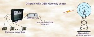
GSM gateway provides a direct connection of a corporate phone system with GSM network that cut down expensies charges on a mobile connection (usually in the companies) and gives the saving rate.

Two SIM cards of communication statements with as much as possible favorable tariff plan are installed in a GSM gateway. Wereupon the GSM gateway starts operate as mobile phone of GSM network connected to a stationary network. The network administrator includes in the list of telephone numbers of employees who should have access to the gateway. All stationary and mobile subscribers of such network can make out coming calls at the lower cost.
The GSM gateway has also PBX trunk.

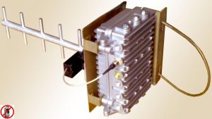
For reception of GSM signal from the base station the external antenna is connected to a matching connector on the front panel of the gateway case.

It is possibly to connect 4 and more SIM cards on the customer’s request .


SPECIFICATIONS

Supply voltage 220V
Current at pick up 30mA
Voltage at hang up 48V
Power consumption, no more than 50 W
Other parameters of GSM gateway correspond to the GSM standards.

JAMMER OF THE CELLULAR PHONES SIGNAL OF GSM 900/1800 STANDARD

Jammer  “JAM” is intended for blocking (suppression) of the signals in 890….960 MHz and 1710…1880 MHz frequency ranges. At device switching on all cell phones which are in this range beginning operates in  searching mode.

It is recommended to apply:

  • in conference halls;
  • in theatres, libraries, cinemas, churches, temples, in hospitals;
  • on the territory of special objects;
  • at schools and institutes of higher education;
  • for security services (antiterrorism, blocking of listening in, «bugs» in the given range).

The system has 2 independent radiofrequency sections with two direct antennas of both GSM ranges.

The following modifications   are suggested:

JAM- Out  — operating out-of-doors. In this case the level of output power is not adjustable.

JAM- In  — operating in-doors. In this modification the level of output signal on each channel is stipulated.

JAM  P  — low-power pocket.

Delivery set: 

Unit of cell phones signal supression 1 pc
Antennas for two GSM range 2 pcs
Fastening set and cables 2 pcs
Passport, technical specification and user’s manual

SPECIFICATIONS:

Maximum output power in each range:
JAM Out-4 4W
JAM Out-10  10W
JAM In-100  Up to 100 mW
JAM In-500  Up to 500 mW
JAM In-1000  Up to 1000 mW
JAM P  5 mW


Range of cellular signal suppression, m 
JAM Out-4 Up to 50
JAM Out-10  Up to 100
JAM In-100  Up to 10
JAM In-500  Up to 15
JAM In-1000  Up to 30
JAM P  Up to 5


Supply voltage, V
JAM Out, JAM In(from AC) 220
JAM P(self-contained)  9
Supply voltage, V
Channels number 2
Operating time  is not limited

MODULATORS   FOR  TV-TRANSMITTERS

Modulators are intended for carrier frequency formation and  TV-signal frequency translation (image and sound) to necessary TV- channel frequency.

Modulators are used in TV-transmitters, cable TV systems, MMDS and other systems of TV-signal transmitting.

Carries out:

  • stabilization of sound and image carrier frequencies by the synthesizers based on the thermos-tatted frequency oscillator;
  • forming of signal with single side band by the SAW filter;
  • stabilization of output signal level;
  • indication of video signal absent;
  • indication of over modulation of audio signal;
  • high amplitude and frequency linearity of the section;
  • correction of amplitude non- linearity of power amplifier of the TV-transmitters;
  • balanced input for audio signal.

SPECIFICATIONS

Image  Sound
Frequency range 20…6C106 Hz 20…14C103 Hz
Modulation type amplitude frequency
Nominal level of input signal 1V(at Rinp=75 Ohms) 0,75V(at Rinp=600 Ohms)
Input signal levels range 0,5…1,5 V 0,25…1,75 V
Signal/noise ratio 60 dB 60 dB
Amplitude frequency characteristics unevenness of  video signal ±0,2 dB

Output signal to channel intermodulation products ratio 60 dB
Non-linearity of carrier frequency:
       -in VHF range ± 50 Hz
       -in UHFrange ± 200 Hz
Power supply (220± 20) V
Operating temperature range 5…450С
HF signal output level at Rloading=50/75 Ohms 0,3…3 V

TV TRANSMITTERS «MARK -TV» 

It is intended for TV  broadcasting  on VHF and UHF.
Transmitter provides high quality of transmitting according to international standards.
It operates in continuous mode and don’t needed service.

The transmitters are produced with following output power ranges:
   1…5 W, 5…10 W, 10…20 W, 20…50 W,
50…100 W, 100…200 W, 200…500 W,
1000 W,  2000 W, 4000 W, 6000 W.

In transmitters is carried out:
— microprocessor control;
— full control and diagnosis of all units of transmitter
— parameters set up by hand or automatic;
— automatic start up at video signal.