AUTOMATED CONTROL SYSTEM BY TECHNOLOGICAL PROCESSES (INDUSTRIAL CONTROL ) 

Automated control system of technological processes (ACS TP) is intended for: automation of data collection about of complex defused   complexes of the process equipment and for management of manufacturing process, maintenance of an optimum operating mode of technological apparatuses and accounting of the intermediate data, formation and output of the accounting and archival documentation, diagnostic of the measuring equipment.

The flexible modular structure of  ACS TP  allows providing for each technological object an optimum level of automation, sufficient for effective and safety carrying out of manufacturing process.
We are offering development and adaptation of the software of  ACS TP  under orders of clients with reference to concrete object and equipment.
The implementation of the given system allows to:

  • automate manufacturing process;
  • provide a remote control and management;
  • improve conditions and increase safety of work.

On the central computer the opportunity of management by the manufacturing process from a computer and archiving of the data, the printing of reports and other processes are carried out.

The quantity of controller is determined by demands of the manufacturing process. The controller can operates as in composition of a complex under the control of the central computer, and is independent with an opportunity of manual input of parameters.
The software of the controller develops for a concrete manufacturing process.
Controller includes:

  • measuring unit which includes channels of temperature measurement with thermistor sensor such as NTC 10k (up to 24), channels of analogue signals (up to 8) measurement, channel of voltage and a current measurement (on one), electrically untied from the system;
  • control unit by which the control of four clock step motor (one channel), thyristor module (3 phases) and managing keys such as « dry contact » (up to 8) is carried out.
  • processing unit;
  • unit of indication and communication interface with computer.

The information transmission from controller to the computer and reception of control commands is carried out by using of standard RS232 or RS4222 interfaces.

DATA EXCHANGE SYSTEM ON THE BASIS OF GPRS COMMUNICATIONS 

It is intended for providing of reliable and qualitative communication between two and more unites of the remote and hard-to-reach areas by using of GSM communication net. The system ignores increasing of expenditures dependence on distance between unites, giving bidirectional digital connection and a wide spectrum of possible interfaces of digital and analogue modules, the control and data acquisition in real time for organization of monitoring and control of unitary assemblies.

Universality of the system allows operate with products of world manufacturers: industrial engineering, various types of transmitters of pressure and temperatures, controlled systems of launchers.

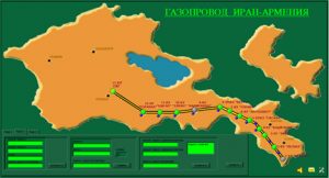
  SCADA SYSTEM

Provides control of difficult technological systems.

Use of the developed software allows creating a server, operating simultaneously with autonomous systems, ready to operate with difficult industrial,  security and other units.

Systems’ advantages:

  • ease and cheapness of program and hardware base changes;
  • increasing of functionality without system substitution;
  • possibility of use of  backup communication channels;
  • operation with various industrial protocols.

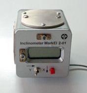
DUAL AXIS LOW COST INCLINOMETER «MARKEL 2-01»

Inclinometer “МаrkEl 2-01” intended for high-precision measuring of angle of inclination in two axis.
It operates both autonomous and as a part of automatic control systems.

Inclinometers with an electric output signal, in proportion to an angle of inclination, are comparative new equipments produced for wide industrial application.

Its high accuracy, small sizes, absence of the mobile mechanical parts and simplicity of strengthening on object do expedient use its not only as sensor of roll but also to change by them angular sensors, and not only on stationary, but also on mobile objects.

Fields s of application:

  • Long-time definition of position’s changes of various high-rise buildings, dams, use in systems of platforms’ horizontalizing, definition of deflections and deformation values of different supports and blocks;
  • Control of slope angles of mobile roads and railways at its building, repair and maintenance;
  • Definition of cars’ roll, road graders and asphalt pavers, cranes, excavating and agricultural machines;
  • Use in robots, machines and printing presses for control of the mechanism position, cutting element or printing presses rolling.
  • Use in the alarm and acoustic control systems.


Features:

Has a linear dependence of output signal from an angle slope in one — so-called working plane and practically does not change the values in other (non-working) plane, thus its signal weakly dependent on temperature change.
For definition of a plane position in space is used two located under 90 ° angle to each other inclinometers.


SPECIFICATION

Range of a measured slope ±5°
Threshold of sensitivity 0, 001°
Linearity from a full scale ± 0,25… 0,75 %
Repetition “0” 0,02°-0,03°
Error at lateral tilt up to 45° ±1%
Equipment time constant 0,1 sec
Bandwidth (-3dB) 0…3 Hz
Temperature coefficient“0” 0,015% / °С
Temperature coefficient of  slope  characteristic 0,04% / °С
Operating  temperature range minus 40 … +60°С
Overall dimension 100x80x80mm
Weight 1,5kg
Coupling with PC RS232

VSWR SENSOR (MB1) AND DETECTOR HEAD (DH1) TO THE R2-102 MEASURING DEVICE 

We are offering the VSWR sensor (measuring bridge(MB1)) and detector head (DH1), which are used in a set with measuring units (sweep frequency generator (SFG) and indicator unit (Я2Р-70) of P2-102 device.

Designation  of P2-102 device are:  panoramic displaying on the indicator  and measurement of VSWR frequency characteristics and attenuation of elements of the coaxial tract. It is used in laboratory and enterprises bay at measurement and adjustment of VSWR parameters and attenuation of various microwave devices.

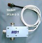
VSWR sensor is a measuring bridge (MB1),which forming signal  proportional to reflection coefficient of the measured device in cross-section of a measuring connector at the expense of comparison of a reflected signal from internal reference loading with a signal, reflected from the measured device. The formed signal of unbalance is detected on the built — in detector and transferred in the measuring block.
It is 6dB resistance divider formed by three resistors; resistance of each is equal to a wave impendence of a coaxial line (50 Ohm).

VSWR sensor (MB1) parameters

Operating frequency 0,01…2,14 GHz
VSWR measurement range 1,05 — 14,0
Tract’s size 7/3,04 mm
Dynamical range 40 dB

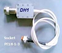
Detector head (DH1) it intended for formation of low-frequency signals proportional to the power level of the microwave signals.
It is used for measurement of the module of transmission coefficient , amplification, attenuation, and for power measurement. Due to using of special designs (with the built — in amplifier with frequency F0=100 kHz) and resent element base the detector head has a bandwidth of frequencies and measured powers, small irregularity amplitude-frequency characteristics, low value of VSWR input.

DH1 Parameters
Frequency range 0,01…4 GHz
Measurable power range minus 20…60 dBm
Limit of effective range of attenuation 0…40dB
Wave impendence 50 Ohm
Input VSWR, no more than 1,2
Tract’s size 7/3,04 mm

MULTICHANNEL DIGITAL ANALYZERS

Multichannel digital analyzers is a high-performance, fast(response) device with a standard PC, intended for checking and characterization of digital circuits. Carries out grouping of input channel in serial bus.

Analyzer’s  operates in two different modes:
  • internal synchronization mode(at recording of input data is used the internal clock frequency oscillator);
  • external synchronization mode (at recording of input data is used the external clock frequency oscillator)

Multichannel digital analyzer includes:

  • module of the logical analyzer;
  • personal computer (PC);
  • software.


Analyzer’s modifications Number of input channel Clock frequency Number of analog inputs
DA 16/20,40,80  16 20,40,80 ———
DA 32/20,40,80  32 20,40,80 ———
DA-À1 16/20,40,80  16 20,40,80 1
DA-À2 16/20,40,80  16 20,40,80 2
DA-À1 32/20,40,80  32 20,40,80 1
DA-À2 32/20,40,80  32 20,40,80 2
DA-À3 32/20,40,80  32 20,40,80 3
DA-À4 32/20,40,80  32 20,40,80 4

Modifications DA-A1…DA-A4 have the additional opportunity to measure the analog signal from 10 mV to 10 V.

SPECIFICATIONS

Memory capacity of data acquisition for one channel 128 Kb
Program decoding of serial bus RS 232, SPI. 12C
PC connection LPT
DC Supply voltage from external source 5V
Max. power consumption 5W
User interface WINDOWS 95/98/NT/XP